

D.I.Y. Accessible Vectrex Controller
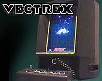
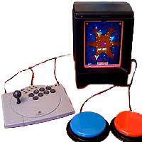
This guide explains how to adapt a digital arcade stick for use with an MB Vectrex (aka GCE Vectrex) and disability standard switches. The Vectrex is a superb, "vector-scan" games machine dating from 1982. Amazingly, new games are still being created, and are readily available by mail-order.
If you're an absolute beginner, we strongly recommend that you follow "The Basic Soldering Guide" - by Alan Winstanley.
SAFETY: Adapting equipment voids the manufacturer's guarantee, and the attempt may cause irreparable damage. Always use adapted equipment under supervision, and disconnect power when not in use. These adaptations are at your own risk. Good luck!
Vectrex links
Vectrex.co.uk
Packrat Video Games
rec.games.vectrex - Google Group of Vectrex fans.
1. What you will need:
- 1x Arcade Stick (almost any will do)
- 8x 3.5mm mono 'headphone' sockets
- 4x 3.3K Resistor
- 4x 10K Resistor
- 1x Strip board
- 1x D9 lead (salvaged from a Sega Megadrive or Vectrex controller, or build your own)
- Shrink Wrap (optional)
- Soldering iron (15 to 30 Watt power); thin solder; soldering flux; de soldering braid; thin wire (e.g. 16 strand 0.2mm).
- Cordless drill with 2 drill bits (1x 1/4"; 1x 2mm); Knife or wire strippers; small screwdriver set.
- Patience. Put aside the best part of a day to adapt these controllers.
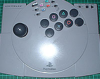
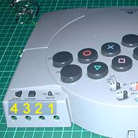
2. Open casing
Open up the controller. The ASCII stick has six screws, with two hidden behind rubber feet.
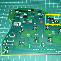
Remove the grey plastic bracket holding the PCB in place. Remove the PCB.
Remove the small silver contacts from the sliding switches to disable these.
3. Drill 8 holes
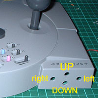
Drill 8 holes as pictured using your 1/4" drill bit. Ensure that your 3.5mm sockets fit neatly and do not touch one another.
That's the easy bit finished, now the tougher bit...
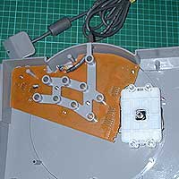
4. Remove original leads
De-solder the original Playstation lead (top right yellow box) and the joystick (bottom left yellow box). The PCB will now simply serve as the contacts for buttons 1, 2, 3 and 4 for the Vectrex.
Free up the 8 wires from the joystick. You will need to connect these later to a simple circuit board.
5. Cutting and Drilling
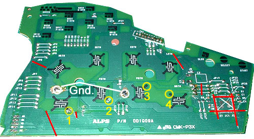
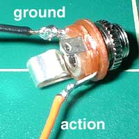
Drill a small hole into four button contacts on the PCB (encircled yellow - click the image for an expanded view).
You will need to drill into the Ground track (the wide light green track that touches all of the button contacts on one side. With an ASCII stick you will need to make two holes (encircled in white).
Cut the tracks (marked red) using a sharp knife, drawing several times away from you. This simplifies the circuit, and helps avoid unpredictable operation.
6. Test your sockets
As not all 3.5mm mono sockets are connected alike, you will need to find which 2 of the 3 contacts you need to solder to.
Attach a test lamp or multimeter to any 2 contacts. Plug in your switch, then press it. If the lamp comes on when pressed you have the right connections, otherwise try a different combination. There's only 3 possibilities.
Attach long enough wires to reach from the holes you have drilled in the casing to the place you intend to mount your circuit board (see later). Use shrink wrap to insulate your soldering on the sockets.
7. Building the Circuit
The tougher bit. Click here for the circuit diagram. Click the image for a larger view.
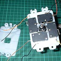
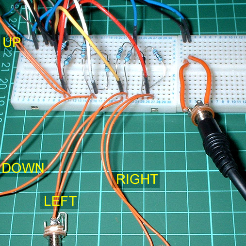
If this is the first time you have built a circuit, you may find it helps to test the circuit using a reuseable bread-board and a number of test leads (top left picture).
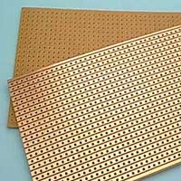
Once you are confident that you can get the circuit to work, transfer it to strip board (pictured left). Try to make your circuit as small as possible bearing in mind the room available to mount it in the Arcade Stick.
Connect up all the buttons, the joystick and the 8 sockets. Find a way to mount the board safely in the Arcade Stick, ensuring that the board will not short circuit on anything metal (use electrical tape to insulate anything).
8. Reassemble and Test
Put everything back together, then test. I recommend using the MB Test cartridge which has a joystick test programme, but in lieu of this, use any game.
If you have any problems, carefully inspect the quality of your soldering, and the accuracy with which you have followed the circuit diagram. Have fun!
D.I.Y. Text and images PUBLIC DOMAIN 2005 - OneSwitch
Analogue to digital circuit and text (c) 1995 Brian Holscher