D.I.Y. C-SID 2
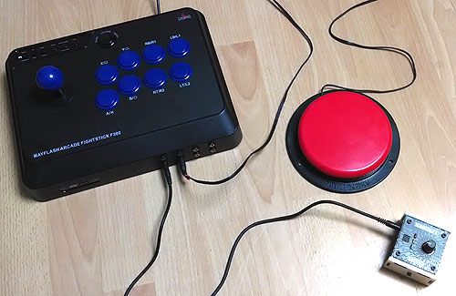
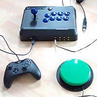
This guide explains how to adapt a Mayflash Arcade Stick F300 to build a versatile accessibility switch interface for use with various game consoles in a variety of ways. Read the user instructions here for more information.
Using a Titan One adapter, this set-up can make many games easier for various playing styles. This includes one-switch play, and playing with a standard joypad controller alongside some additional switches.
If you're an absolute beginner, we strongly recommend that you follow "The Basic Soldering Guide" - by Alan Winstanley. Keep your working area well ventilated.
SAFETY: Adapting equipment voids the manufacturer's guarantee, and the attempt may cause irreparable damage. Always use adapted equipment under supervision, and disconnect power when not in use. These adaptations are at your own risk. Good luck!
Most of the basic components used here are commonly available from Electronics stores such as Maplin Electronics and Farnell. The Mayflash arcade stick can typically be found on Amazon and eBay.
1. What you will need
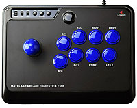
1x Mayflash Arcade Fighting Stick F300
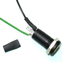
1x On/Off switch
15x 3.5mm sockets (e.g. Farnell "126-7396")
1x Titan One adapter.
Soldering iron (15 to 30 Watt power), thin solder, soldering flux, thin wire (e.g. 10 strand 0.1mm), 3mm shrink wrap (optional).
Cordless drill with drill bits (including 7.5mm and 20mm), knife or wire strippers, small screwdriver set, needle nose pliers (optionally) small hot glue gun.
2. Basic Preparation
Test your arcade stick on a PC using the "USB Game Controllers" ensuring that all is working correctly before proceeding.
Using the pictures below mark pilot holes on the case to drill (with a pencil or light touch of a soldering iron). Aim to position your sockets between the internal thin plastic vertical supports to make life easier.


3. Drill Holes
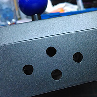
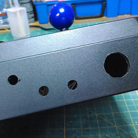
When you are happy with your pilot holes/marks, drill the following:
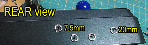
A 20mm hole for the On/Off switch (rear of controller.
Four 7.5mm holes for the joystick sockets. Eight for the front sockets for the blue push buttons and 3 at the the back for the menu buttons.
After drilling, clean all holes up using a knife and/or small file. Where anything would obstruct mounting your sockets, carefully cut and file it away. Have a cup of tea.
4. Wiring up
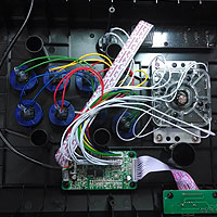
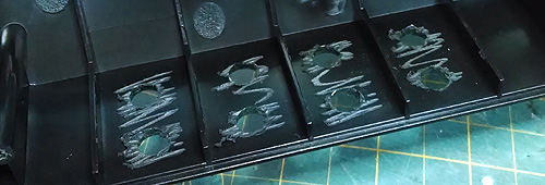
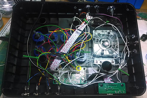
The really laborious bit. Use two different colours of wire as pictured. Treat the black wire as the common wire (or ground) and the green side being the individual control wire.
Be methodical - and be patient. Use heat shrink or electrical tape to insulate all spliced wires. This section will take a long time, following the pictorial guide below. Have some good music on is an idea.
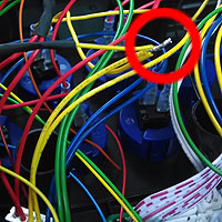
GROUND LOOM HELP: Link all black ground wires together from all the sockets. Wire this to the ON/OFF switch (not pictured above). Next solder a ground wire from the other blade of the on/off switch and connect it to any odd wire on the shapes connector block (1,3,5 or 7). I tend to use the first green wire under A/X on the top right of the main circuit board (encircled in yellow above).
BLUE Buttons: Carefully disconnect the block connector for RT/R2 (Red), RB/R1 (Yellow), LT/L2 (Blue) and LB/L1 (Green) (these should be labelled on the PCB). Cut each 2nd coloured wire and splice into the appropriate socket. Use shrink wrap to insulate the exposed wires.
JOYSTICK: From left to right, splice into UP = 2, LEFT = 4, RIGHT = 6, DOWN = 8.
START: Start connects to the second white wire that connects to the top middle plug of the main PCB.
HOME and SELECT: Disconnect the ribbon cable from the top push-button circuit board. HOME connects to the 3rd wire of the ribbon cable, and SELECT connects to the 4th.

5. Reassemble and Test
Put everything back together, then test. If all is well, and looks good, tidy up with cable-tidies and hot-glue where appropriate.
If you have any problems, carefully inspect the quality of your soldering, and the accuracy with which you have followed the wiring up guidance. Basic instructions here.
6. Programme Titan One

Titan One scripts here and instructions here. Please get in touch for help.
D.I.Y. guide PUBLIC DOMAIN 2017,18 - OneSwitch.org.uk