

D.I.Y. "Speech" Device
Adapting for switch use
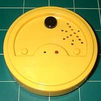
This guide explains how to adapt a 'Talking Tins' speech device for disability standard switch use. However, this technique follows for almost all speaking devices, including novelty speaking cards.
If you're an absolute beginner, we strongly recommend that you follow "The Basic Soldering Guide" - by Alan Winstanley.
SAFETY: Adapting equipment voids the manufacturer's guarantee, and the attempt may cause irreparable damage. Always use adapted equipment under supervision, and disconnect any batteries when not in use. These adaptations are at your own risk.
You can obtain a pack of three 'Talking Tins' for around £10 from TalkingProducts. There is an upgraded Talking Tin now with a 30-second recording memory for a little more money. All other components are commonly available from Electronics stores such as Maplin Electronics.
Buy pre-adapted: You can buy ready to go adapted 'Talking Tins' from the OneSwitch shop.
1. What you will need
- 'Talking Tins' unit; 3.5mm mono headphone socket; thin wire (e.g 7strand 0.2mm).
- Soldering iron (15 to 30 Watt power); thin solder; soldering flux; desoldering braid.
- Cordless drill with 2 drill bits (1x 1/4"; 1x 2mm); knife or wire strippers; small screwdriver set.
2. Drill a hole
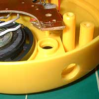
Open up the casing. Make a small pilot hole where there is enough space to house your 3.5mm socket. Drill a 1/4" hole as pictured, being careful to stop as soon as you're through.
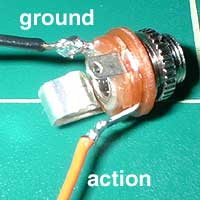
3. Remove this contact
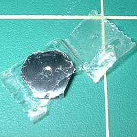
Removing this switch contact renders the black 'speak' switch useless, but is essential.
4. Switch contacts
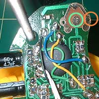
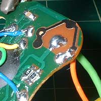
The Green and Orange circles mark the points of the 'speak' switch circuitry that you need to solder a 3.5mm mono switch socket to. You will need to drill a hole through the encircled Green point...

Scribe a small pilot hole in the board, then very carefully drill a 2mm hole as pictured.
6. Solder your socket
As not all sockets are connected alike, you will need to find which 2 of the 3 contacts you need to solder to.
Attach a test lamp or multi-meter to any 2 contacts. Plug in your switch, then press it. If the lamp comes on when pressed you have the right connections, otherwise try a different combination. There's only 3 possibilities.
Solder two lengths of wire to the socket. Expose the ends, tinning them if you wish.
7. Solder to the PCB
Solder your socket to the Printed Circuit Board (PCB) switch connections, aiming to have nothing jutting out from the board.
Blow on the board to cool it down as soon as the solder flows. Too much heat could damage the workings of the device.
8. Reassemble
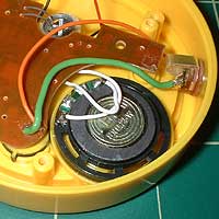
Put the PCB back in place, and screw the 3.5mm socket into the casing. Test the device with a switch. If all seems OK, put it all back together being careful, when tightening up the socket, not to twist the wires too much.
If the unit won't screw back together neatly due to the socket spoiling on the casing, try cutting a little away from the casings inner lip.
9. Full Test

Test the unit with a switch several times, then leave it alone for a few minutes. If it activates by it's self repeatedly, there's probably a short circuit. Pull it apart again, and examine the accuracy of your soldering carefully, especially on the socket.
If the sound seems quite muffled, open the unit up again, and move the wires away from the speaker vents.
Text and images PUBLIC DOMAIN 2004 - www.OneSwitch.org.uk
TalkingTins (c) Talking Products Ltd. - www.TalkingProducts.co.uk