

D.I.Y. Game Console Switch Interface Deluxe
This guide explains how to adapt a Sega Dreamcast Arcade Stick to build a versatile accessibility switch interface for use with Playstations.
Using additional joypad adapters many other computers and games consoles can be made more accessible too. These include PCs, Xbox 360, Dreamcast, Gamecube and more. On a PC this controller can act as a mouse and any key on the keyboard using JoyToKey.
If you're an absolute beginner, we strongly recommend that you follow "The Basic Soldering Guide" - by Alan Winstanley.
SAFETY: Adapting equipment voids the manufacturer's guarantee, and the attempt may cause irreparable damage. Always use adapted equipment under supervision, and disconnect power when not in use. These adaptations are at your own risk. Good luck!
Most of the basic components used here are commonly available from Electronics stores such as Maplin Electronics and Farnell. The SEGA Arcade Stick can readily be found on eBay.
The iPac circuit board and Playstation 2 adapter can be purchased directly from Ultimarc. It is very important that you specify in a follow up e-mail to Ultimarc that the Playstation 2 adapter must be fitted with the OneSwitch.org.uk specified chip, and that the adapter must also be the latest model. You will need to program the chip using the "Win iPac Interactive Panel Designer" and included key assignment file. Any problems, just get in touch.
To make things easier, you can also buy a ready programmed iPac with adapter, or even a completely built C-SID controller, from OneSwitch. There's a list of great accessible Playstation 2 games over at SpecialEffect's Accessible Gamebase.
1. What you will need

- 1x Sega Dreamcast Arcade Stick
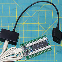
- 1x Ultimarc iPac board with USB PC lead.
- 1x Ultimarc Playstation adapter with case, fitted with latest PCB and OneSwitch.org.uk control-set chip.
- 1x PS/2 to PS/2 connecting lead
- 1x USB Keyboard
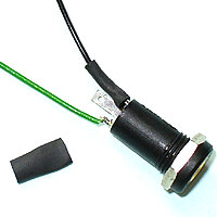
- 1x On/Off switch (e.g. Maplin's "JR96E")
- 3x Small push switches (e.g. Maplin's "FH59P")
- 27x 3.5mm sockets (e.g. Farnell "126-7396")
- Strip Board (e.g. Maplin's "JP50")
- 4x M3x12MM nuts and bolts
- Soldering iron (15 to 30 Watt power); thin solder; soldering flux; de soldering braid; thin wire (e.g. 10 strand 0.1mm), Shrink Wrap (optional).
- Cordless drill with drill bits (including 7.5mm and 20mm); Knife or wire strippers; small screwdriver set; Needle nose pliers; Small hot glue gun; Pencil; Pin.
Patience and time. And again - if you need any help or advice - feel free to get in touch.
2. Basic Preparation
Flip the controller over (rest it on something soft to avoid scratching it). Remove the six black screws then remove the metal cover.
Remove all three white connector blocks from the PCB. Discard the long grey Dreamcast lead.
Remove and discard the PCB. Remove the grey plastic VMU housing in place. Keep this and all screws safe.
Cut the white connector blocks off the Joystick and Button wiring.
Check the existing wiring. If anything looks loose (especially the start button) - consider resoldering or hot glue-ing to make stronger.
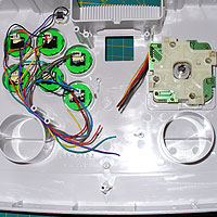
Now you'll need to mark the drill points on your casing. Use a pencil and use the following three pictures as your guide...


3. Drill Holes

When you are happy with your pencil markings, melt a guide point for each hole using your soldering iron. Be careful not to inhale the vapours. Drill the following:
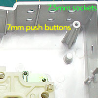
A 20mm hole for the On/Off switch (rear of controller in line with black "Z". :
Three 7mm holes at the top for your three small push buttons, and three 7.5mm holes beneath these for the relating sockets.
Twenty-seven 7.5mm holes for the rest. Yes - things are about to get messy!
After drilling, clean all holes up using a knife and/or small file. Where anything would obstruct mounting your sockets, carefully cut and file it away. Have a cup of tea.
4. VMU Window Guard
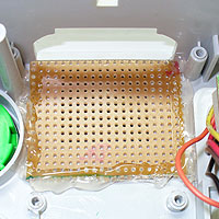
Cut a 16 x 20 rectangle of strip board. Hot glue in place as pictured. This provides protection to the PCB.
5. iPac Mounting
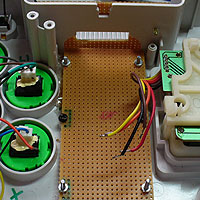
Cut a 20 x 46 rectangle which is for mounting the iPac to. Cut off the mounting notches for the old PCB that rise above the four screwing mounts.
Place the strip board as close to the back of the controller as possible. You will likely need to cut away a few small areas to make it fit neatly.
Using the pre-drilled mounting holes as your guide - drill four points on the strip board that will enable you to screw the board to the Dreamcast arcade stick.
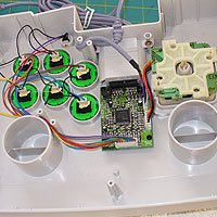
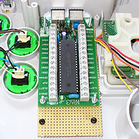
Line up the iPac PCB as pictured. Mark the strip board through the four mounting holes. Drill these holes then push four long bolts up through these holes, and affix with a nut.
Mount the strip board to the arcade stick using your four black screws. Position the iPac over these bolts and fix into place with a further four bolts. Ensure that the two round PS/2 sockets can be comfortably accessed through the old VMU slot. Hot glue over any spots that may interfere with the iPac's operation.
6. Rear Guard

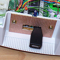
Mark out a window for access to the two rear PS/2 round sockets front and back (pictured left). Poke a piece of wire through to help you match up your markings.
Cut repeatedly across your markings front and back then drill holes within this rectangle. Carefully nibble away the remaining strip board using pliers. Use a small file to tidy up the rectangular hole.
After ensuring that your hole is large enough, drill two 2.5mm holes through the strip board into the plastic of controller casing. Use the two remaining brass screws to screw into place.
7. Wiring up
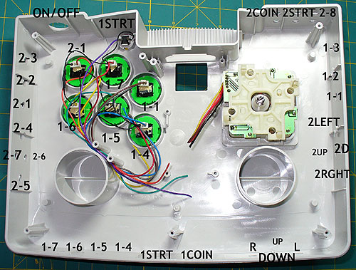
The really laborious bit. Use two different colours of wire as pictured. Treat the black wire as the common wire (or ground) and the green side being the individual control wire.
Be methodical - and be patient. This will take a long time, following the pictorial guide below. Zzzzzz.
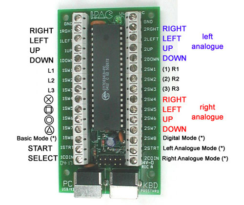

GROUND LOOM HELP: Link all black ground wires together from all sockets and the three small push buttons. Wire these to the top blade of the on/off switch.
Next solder a ground wire from the bottom blade of the on/off switch and connect it to either one of the GND terminals on the iPac.
Connect the (normally grey) ground loom wire from the green push buttons to a GND. Do the same for the (normally black) Joystick ground wire.
The Dreamcast Arcade Stick wiring is normally as follows: RED (Right) - YELLOW (Left) - BROWN (Up) - ORANGE (Down) - PURPLE (Start) - BLACK (Ground) - GREY (Ground).
8. Reassemble and Test

Put everything back together, then test. If all is well, and looks good, tidy up with cable-tidies and hot-glue where appropriate.
If you have any problems, carefully inspect the quality of your soldering, and the accuracy with which you have followed the circuit diagram. Have fun!
D.I.Y. Text and images PUBLIC DOMAIN 2008 - www.OneSwitch.org.uk