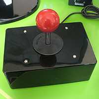
D.I.Y. Ultrastik

This guide explains how to build a simple USB Analogue Joystick with optional accessibility switch sockets for use with PCs and Macs.
On a Windows PC the functions of this controller can be set to any mouse or keyboard function using JoyToKey. All kinds of functions can be assigned to the buttons including latching, auto-fire and profile switching. Using a Windows PC and Cronus Max adapter this can also be used on the Playstation 3, Xbox 360 and Xbox One as is or with additional controls.
If you're an absolute beginner, we strongly recommend that you follow "The Basic Soldering Guide" - by Alan Winstanley.
SAFETY: Always use DIY equipment under responsible supervision where appropriate, and disconnect power when not in use. These adaptations are at your own risk. Good luck!
Most of the basic components used here are commonly available from Electronics stores such as Maplin Electronics and Farnell. The Ultra-Stik 360 is available from Ultimarc along with the free configuration software.
1. What you will need
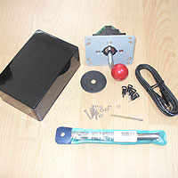 1x Box (try searching the likes of eBay for "ENCLOSURE 150 X 100 X 60MM"). A heavy duty version might be the Hammond 1455N1601 (160 x 103 x 53mm) needing M3.5 / M4 bolts to secure.
- 1x Ultimarc Ultra-Stik 360 and UltraMap Utility.
1X Ball-top alternative (if you don't like the colour: Seimitsu LB-30 mm for standard ball-top, LB-35 mm for balls to fit chunkier bat version - Arcade World a good source). - 4x M3 nuts and bolts with washers.
- 1x P-clip.
- Blue-tack.
- Velcro (e.g. from Trabasack) or rubber-feet.
- JoyToKey with custom profiles.
- Optional: 1-8 3.5mm switch sockets (e.g. code 126-7396 from Farnell Electronics).
- Recommended: A mounting system such as velcro based Maxcess trays or Trabasacks.
- Soldering iron (15 to 30 Watt power); thin solder; soldering flux; thin wire (e.g. 10 strand 0.1mm), Small file set, Shrink Wrap (optional).
- Drill with drill bits (including 3mm, 4mm, 7.5mm and 15mm); Knife or wire strippers; small screwdriver set; Needle nose pliers; Small hot glue gun; Pencil.
- Ball-tops are M6 thread. See the OneSwitch Blog for some examples.
2. Configure the Joystick
The Ultramap utility which you can download freely from Ultimarc allows you to change the function of the joystick. Choose "Analog" for compatibility with JoyToKey and additional switch sockets. Choose "Mouse" if you'd like the joystick to act as a mouse pointer alone.
This is a good time to work out where UP and DOWN are on your joystick. Mark or Scribe the UP position onto the base of the joystick to help you later.
3. Making Holes
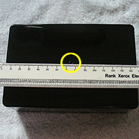

Drilling holes neatly needs time and patience at this stage:
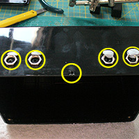
Joystick (1x 15mm main hole and 4x 3.5mm mounting holes): Measure to the precise centre of the top of the box then make a pilot hole. Drill a 15mm hole in the dead centre of the top of the box (you may need a corded drill for a drill bit this size or an adapter). Next use four bits of blue-tack to position your joystick as centrally as you can. Mark four pilot holes through the underside and drill 4x 3.5mm holes.
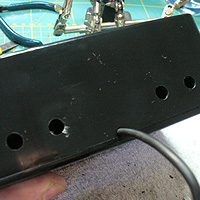
USB cable exit hole: Simple way is to make a central 4mm pilot hole for the USB wire as pictured. Use files to fit. Alternatively, perhaps a 10mm hole for a DM2 strain relief grommet 6mm up.
Optional Switch Sockets: Make pilot holes for your 1-8 switch sockets then drill 7.5mm holes for each (if using Pro-Signal sockets). I find using a bit of blue-tack helps me line the sockets up as I want them.
4. Fit joystick

Secure the joystick using 4x M3 nuts and bolts with washers. Tighten using pliers and a screw-driver ensuring that the joystick is as central as possible, with no restiction when you move it in all directions. Consider hot-glueing the nuts into position when finished.
5. Secure USB cable

Connect the USB cable to the Ultra-Stik PCB and then secure the cable to the case using a "P-clip" as pictured.
6. Wiring up
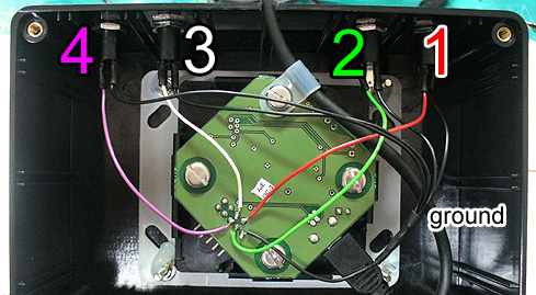
Up to eight on/off switches or switch sockets can be directly wired to the PCB. The five pins nearest the outer edge of the PCB from left-to-right are GND, 2, 4, 6, 7. The pins below them are 1, 3, 5, 8.
If using the Ultimarc connector, the colours are likely:
1 - BROWN
2 - RED
3 - ORANGE
4 - YELLOW
5 - GREEN
6 - BLUE
7 - PURPLE
8 - GREY
GND - BLACK
You can quickly test these using the Joystick controller utility in Windows (see Testing below).
7. Hot Glue

Optionally hot-glue your wiring in place to give extra strength to the connection.
8. Fit Velcro or feet
Fit some velcro on the base of the joystick and/or feet to increase the stability. I recommend Maxcess or Trabasack mount systems.
9. Test
Hold the Windows key + "S", type "USB", click on "Setup USB game controllers, then double-click on 'Ultimarc Ultra-Stik Player 1'). Test your joystick and buttons are functioning correctly. Inspect your soldering if there are problems. Try reprogramming the joystick as something else, then back to "Analogue" via the Ultimarc utility if there are any USB connection faults.
Use JoyToKey to test and reprogramme your joystick to act as mouse/keyboard. Use a Titan adapter to use on other consoles. Contact OneSwitch for more help.
D.I.Y. Text and images PUBLIC DOMAIN 2014, 2018 - www.OneSwitch.org.uk