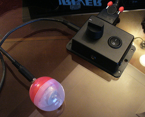
Tentacular Vibro Capsule
This guide explains how to adapt a wired Xbox 360 Microsoft Joypad for improved access for some otherwise disabled people..
You can add switch sockets, an external "mini-joy" thumb-stick, vibro-capsules and a VRAA! box. The latter is designed as a speed restrictor for driving games, ideal for switch users who find a car/vehcicle too fast to control.
As is, this set-up will work on an Xbox 360 or Windows PC. Adding an ULTRA pack to this set-up, brings even greater control and the possibility of control over PS3, PS4 and Xbox One.
1. A-PAC Introduction
The Ultimarc A-PAC is the root controller board. When connected to a PC by the supplied USB cable, it is recognised as two separate joystick controllers. Screw terminals on the board make it easy to connect on/off and proportional controls.
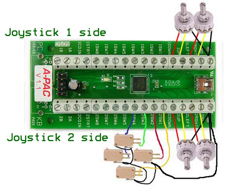
- 32 screw-terminal connectors allow you to connect on/off push-buttons, accessibility switches and digital joysticks. For example, connecting a switch between the GND terminal and 1SW1 terminal makes the switch act as "Button 1" on Joystick 1. N.B.bear in mind that 1STRT is reserved as a special shift function.
- Attaching a switch between 1STRT and GND creates a "shift" control (much like on a computer keyboard) giving your buttons a potential second function. For instance the terminal 1SW1 which is normally assigned as button 1, becomes button 17 when shifted.
- Up to four single-axis analogue potentiometers can be attached (as pictured above), such as four dials/pedals or two thumb-sticks. See the Extras section below for more guidance on this.
2. JoyToKey Introduction
JoyToKey is software that converts joystick input into keyboard and/or mouse output. It uses a profile system for setting up your controls as you need them. Once mastered, JoyToKey can make a PC hugely more accessible.

Test controls then assign a function. The YouTube video below shows the absolute basics with a single switch.
- Mouse control is possible. Several methods can be used to give the user the accuracy and speed they need. It's possible to use a joystick or even just one or two-switches.
- Special features include: auto-repeat, latching, control binding (trigger up to four keys simultaneously from one-button), key-cycling, temporary control-shifting and profile swapping.
- Advanced use of profile switching can enable one or two-switch control over a huge range of possibilities, as seen in this Two Switch Accessible Music Mix Demo.
- Automatic start-up is possible.
- JoyToKey can be registered for free by contacting the author and stating the accessibility purpose you have in mind. If you wish to register at full cost, the price was $7 at the time of writing. However, it is not necessary to register as all functions remain intact.
- Accessibility profiles can be found at the OneSwitch JoyToKey page or by contacting me directly. The full original instructions and most up to date download can be found at joytokey.net.
3. DIY Guide
SAFETY: Always use adapted equipment under responsible supervision, and disconnect power when not in use. These adaptations are at your own risk. Good luck!
Most of the basic components used here are commonly available from Electronics stores such as Maplin Electronics and Farnell. The A-PAC PCB can be sourced from Ultimarc. The packed lunch box from ASDA.
For additional help with this adaptation, please feel free to contact me directly at OneSwitch.
What you will need
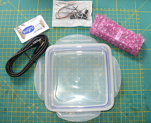
The parts needed for a basic four-socket interface (from top left clockwise): SUGRU, switch sockets and wire, Ultimarc A-PAC, Tupperware sandwich box, USB lead and (not pictured) 4x M3 nuts and bolts. Many alternatives are possible.


1x Ultimarc A-Pac with USB cable
4x 3.5mm mono sockets (Farnell code "126-7396") or similar alternative. Add or reduce sockets as needed.
1.5m of 10 strand / 0.1mm wire. For ease of recongnition try to obtain 4x 15cm coloured and 4x 18cm black lengths. You can use almost any wire, but this size is nicest for threading through the recommended sockets.
2x Sugru 5g pouches.
1x ASDA 600ml clip lid sandwich box or consider an alternative if more style and/or space is needed.
4x M3 nuts and 12mm bolts. Specify "slotted pan head" style bolts if you wish to use with a small flat screw-driver.
Socket drilling guide template to download then print out.
Tools: Cordless drill with 3mm, 7.5mm and 9mm drill bits; Knife or wire strippers; small flat headed screwdriver; pliers; Blue-tack; pencil; scissors.
Optional: Small craft files.
Patience and time. If you need any help or advice feel free to get in touch.
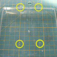
Switch Socket Holes


Cut out your switch socket template rectangle and then blue-tack it inside your sandwich box as pictured. This simply helps you to line up your four switch sockets neatly.
Carefully scribe a small pilot hole/dent using a knife or screwdriver in the dead centre of each template socket.
Drill your switch socket holes using a 7.5mm drill bit. Tidy with a file and/or knife.
Adjust this method to take into account fitting extra components or if using a different style of enclosure/box.
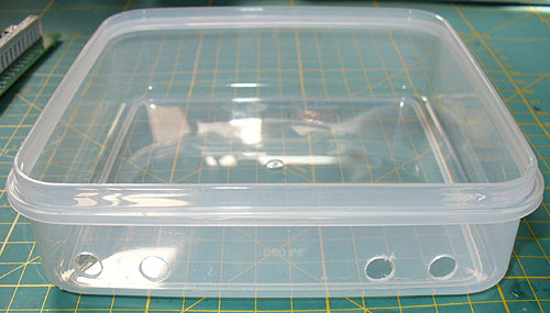
Drill your switch socket holes as above which leaves room for the lid to clip down at the front. If you need many more holes you may need a bigger box/container.
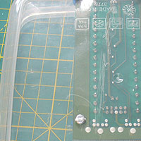
A-PAC holes


Next blue-tack your A-PAC into position, with the mini USB connector as close to the back of the box as you can get it (as pictured).
As before make a small pilot hole/dent right in the middle of the USB connector. Remove the A-PAC then drill a 9mm hole as pictured left, encircled in yellow.
Replace the PCB, then line it up carefully with the hole. If you can plug your USB cable through the hole you've just made, move onto the next stage. If you can't, carefully, file/drill your hole so that you can.
Bolting the A-PAC down
With your A-PAC fixed in place with Blue-tack and the USB cable attached, drill through four 3mm holes (as pictured above and below) and tidy with a file/knife. If accurate, you should be able to thread the four M3 12mm bolts from underneath the casing, up through the A-PAC for you to be able to bolt into place from above.
N.B.Ensure you protect the surface you are working over. I'm using a bit of Jenga wood and an old cutting mat in the picture above.

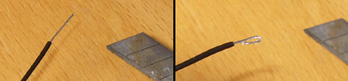
Wire up Sockets


Remove the silver bolt from your sockets (not as pictured - I forgot in this photo). Thread the black ground (GND) wire through the short gold post, and a coloured wire through the opposite short silver post.
Try to keep all the wire threads very tidy and wrapped as tightly as you can around the posts. They shouldn't wobble around much if you've done this well. Use a flat-headed screw-driver to help.
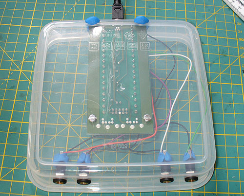
Fit sockets and SUGRU

Carefully push your four sockets through the four 7.5mm holes, then screw them up tight. If your connections to the sockets still look good, take some SUGRU and fix them into place. Put some over the exposed nuts and bolts to stop them coming loose and to make them less likely to scratch anyone.
Connect all four black ground wires into the A-PAC "GND" screw-terminal postiion. Make sure the wire is exposed at the end by carefully cutting away the black plastic sleeving if needed. I recommend folding the exposed wire back on itself as pictured below to give more for the screw-terminal to grab onto.
Next expose and fold each coloured wire. I recommend treating the sockets as switch sockets 1-4 (from left to right) then connecting the attached wire to 1SW1 - 1SW4 in logical order.
Next gently flip your interface box over, and place the two blobs of Sugru over the exposed bolt heads at the back (as pictured below). This should help prevent the interface box from scratching any delicate surfaces in the future.
Testing and Trouble Shooting

Download and start JoyToKey, then begin testing and experimentation.
Click within the JoyToKey window (to give it focus), plug in your switches and hopefully if you hold down all four, you'll see Buttons1-4 highlighted in yellow. Releasing them should see them revert to white. If not, inspect your wiring and that you have followed the guidance as above. Double click on a button number to assign it a function (as seen in this video clip).
No response? Is your USB cable connected firmly? Try reconnecting. Try also taking a short length of wire (or paper-clip) and connecting the GND switch to any other to see if you get any response in JoyToKey. Ensure that nothing is ticked in the "Suspend" menu option.
Use Notepad or Word to test if your assignments are working correctly. All being well, the next thing to do is to learn how to use JoyToKey and to consider some extras.
4. Extras
A. Adding an ON/OFF switch
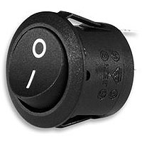
It's useful sometimes to be able to turn off switch access, especially if trying to set things up for users who need help with menus but are a bit "press-happy" whilst you're setting them up.
You can drill/cut in a number of on/off switches (such as Maplin's "JR96E" as pictured which requires a 20mm drill bit). You need to insert your on/off switch between the A-PAC GND terminal on one-side, and the ground wires of your chosen controls on the other.
N.B.JoyToKey has this feature already. See the "Suspend processing of joystick input (temporarily)" option.
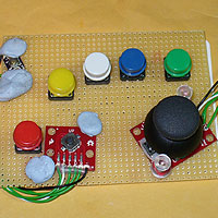
B. Adding a Digital Joystick

There are a huge range of digital joysticks that can be used with the AT Lunch Box system. Click on the red topped joystick left to find out more.
C. Adding Analogue Controls


Under Construction: Adding analogue controls.
Single rotary panel mounted potentiometer (10K Linear 16mm - code 1684813 from Farnell). As used with many driving analogue pedals for steering controllers and with the VRAA! device.
SparkFun "Thumb Joystick Retail".
Alternatives include hacking existing analogue game controllers and trying Farnell or eBay (search on "2 potentiometer joystick") and looking at Altheris industrial (v.expensive) joysticks.
N.B.Analogue controls are only recognised when connected to into the Joystick 1 and/or Joystick 2 directional terminals (need to demonstrate this). See Ultimarc's A-PAC page for further help.
D. Alternative boxes

Obviously, a sandwich box is not the coolest housing in the world for a switch interface. That it's cheap, readily available and transparent makes it a good basic opening choice.
Alternatives are many beyond conventional enclosures or tupper-ware boxes. When choosing, keep in mind the end-user, safety and practicality.
E. Break-out Controls
Under Construction: Buildling quick prototype controls and adding additional controllers.
Breadboards, HobbyTronics, SparkFun.com, SUGRU and Blu-tack. Additional use of Makey Makey and the likes of GlovePie for additional speech control.
Cronus
Xbox 360 and PS3 control is possible by using a Cronus Device and their free to download Bullseye software:

- Navigate the Xbox and PS3 menus and access applications and games using a wide array of alternative access controls, including just two-switches (see video below).
- Take all of the power of the A-PAC and JoyToKey and apply it to JoyToKey. You can add additional controls too if helpful, such as a standard mouse or speech control using GlovePie.
- See Cronus for more information and download Bullseye from their downloads page. The profile I recommend for PS3 use can be downloaded here. A Windows PC is required for this to work.
D.I.Y. Text and images PUBLIC DOMAIN 2013 - www.OneSwitch.org.uk