Tentacular Mini-Joy
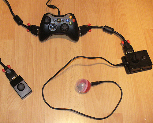
TO DOOOOOOOOO This part of the Tentacular guide explains how to build a Mini-Joy, which is in effect an external analogue thumb-stick.
You can optionally add a 3.5mm switch socket for an accessibility switch and/or a 2.5mm socket to connect a Vibro-Capsule.
As is, this set-up will work on an Xbox 360 or Windows PC. Adding an ULTRA pack to this set-up, brings even greater control and the possibility of control over PS3, PS4 and Xbox One.
1. Start Case Preparation

Use a Dremmel cutting then grinding bit, or soldering iron, knife and/or screw-driver to carefully remove the central pole.
Next, rough up the inner floor of the case as pictured. Scrape off loose deposits with a flat-headed screw driver. This will help later when mounting the thumb-stick with SUGRU and hot-glue.
2. Remove the PCB
Remove all seven screws, including the one hidden behind the bar code sticker.
With the controller face down, remove the back of the joypad that holds the guts of the controller, being careful to free the vibration motors from inside the front grips.
Next remove the PCB from the back of the case.
If you are planning on making a "Vibro Capsule" mark each motor as LEFT or RIGHT. Either way, unplug or cut off the motor/s you will no longer have space for depending on your choice of adaptation below.
3. Decide your needs
Depending upon your needs, decide if you need one or two VGA style D15 female sockets fitted (one per grip). Be warned that many VGA cables are not fully wired, meaning that pins 6, 7 8 and 10 are unlikely to be useable for any extra controls.


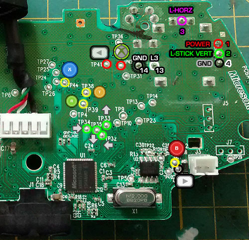
Pins 5 and 15, normally used to carry the POWER and GND lines for a vibration motor, could be used instead to carry two button signals (e.g. button A and B).
GND/Common (to the right of TP42) = L3 GND (PIN 14).
TP32=LEFT, TP33=UP, TP34=RIGHT, TP35=DOWN.
TP38=Y, TP39=A, TP43=B, TP44=X
01L-STICK POWER VCC 1.6v (red wire 12cm)
02L-STICK VERT (green wire)
03L-STICK HORZ (purple wire)
04GND (black wire)
05L MOTOR + (OPTIONAL red)
13L3 BUTTON (OPTIONAL white)
14L3 GND (OPTIONAL black)
15L MOTOR - (OPTIONAL black)
09TRIGGER AXIS (not used here)
11TRIGGER POWER (not used here)
12TRIGGER GND (not used here)
4. Make a D-Sub Hole
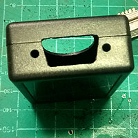
Lots of patience is needed to make a neat hole. Try drilling out a 7.5mm hole in the centre, with two 4mm holes either side. Use a soldering iron and files to make the D25 sub connector fit the hole.
The left and right most corers of the hole (with the lid off) should be around 12mm away from the edges.
Drill two 3mm holes for fixing the D25 sub connector later on.
5. Drill hole/s for socket/s
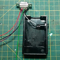
Optionally, for a 3.5mm switch socket (for L3/LB or R3/RB) drill a 7.5 mm hole (in black on the right side in the picture). Wire the socket up to pins 13 and 14 on your SVGA socket (see below).
Optionally again, if you wish to connect a vibro-capsule, drill a 6mm hole on the other side to fit a 2.5mm mono socket. Wire these up to pins 5 and 15 on your SVGA socket (see below).
6. Wire up your thumb-stick
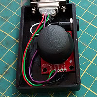
Fit your thumb-stick to the spark-fun PCB. Bend the pins against the board (make sure they are not touching one another). Solder them into place. Next solder the wires from the D15 socket to the board.
VCC = RED (PIN 1)
VERT = GREEN (PIN 3)
HORZ = PURPLE (PIN 2)
SEL = [DO NOT CONNECT]
GND = BLACK (PIN 4)
Thumb-stick: If you want the thumb-stick button to work, you will need to cut the traces that lead to the push-button, and wire pins 13 and 14 to the surface mounted contacts directly under the switch.
Alternatively, carefully wire your socket to the under-side of the PCB connectors if you have cut a thumb-stick out of an existing controller. Observe the correct polarity. You may need to cut traces and/or make alternative links on the board. Test before moving onto the next stage.
7. Test
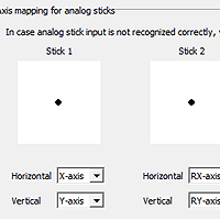
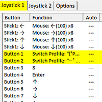
Connect your Mini-Joy to your adapted Xbox 360 joypad. Start JoyToKey > Settings > Configure Joystick > 2. Advanced setting for each device.
Make sure the selected device is your Xbox controller and says "connected", and that it's set as Joystick 1. Now roll the thumb-stick around to ensure it is functioning correctly. Test the switch in the main JoyToKey window too.
8. Fix the thumb-stick
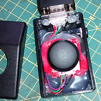
Roll up 10g worth of SUGRU (2 small packets) and create a ramp for the thumb-stick to sit on. Check the position is okay by testing with the lid on and rotating the stick 360 degrees.
Use hot glue and files to correct the position of the thumb-stick and to avoid it rubbing on the top half of the case.
9. Glue the case together
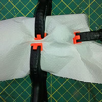
Carefully glue around the inner edges of the case (top and bottom halves). Use a pool of hot glue to attach the top and bottom parts of the case. Cover and clamp for 24 hours.
D.I.Y. Text and images PUBLIC DOMAIN 2014 - www.OneSwitch.org.uk


